PIC18F4550 Programming Tutorial in Hardware C
PIC Tutorial , Mplab IDE - C18 compiler toolsuite
PIC18F4550 tutorial, Looking the data sheet | Ports
PIC18F4550 Programming method 1 Project Blink led
PIC18F4550 Programming Method 2 Blink led
PIC18F4550 programming tutorial method 3
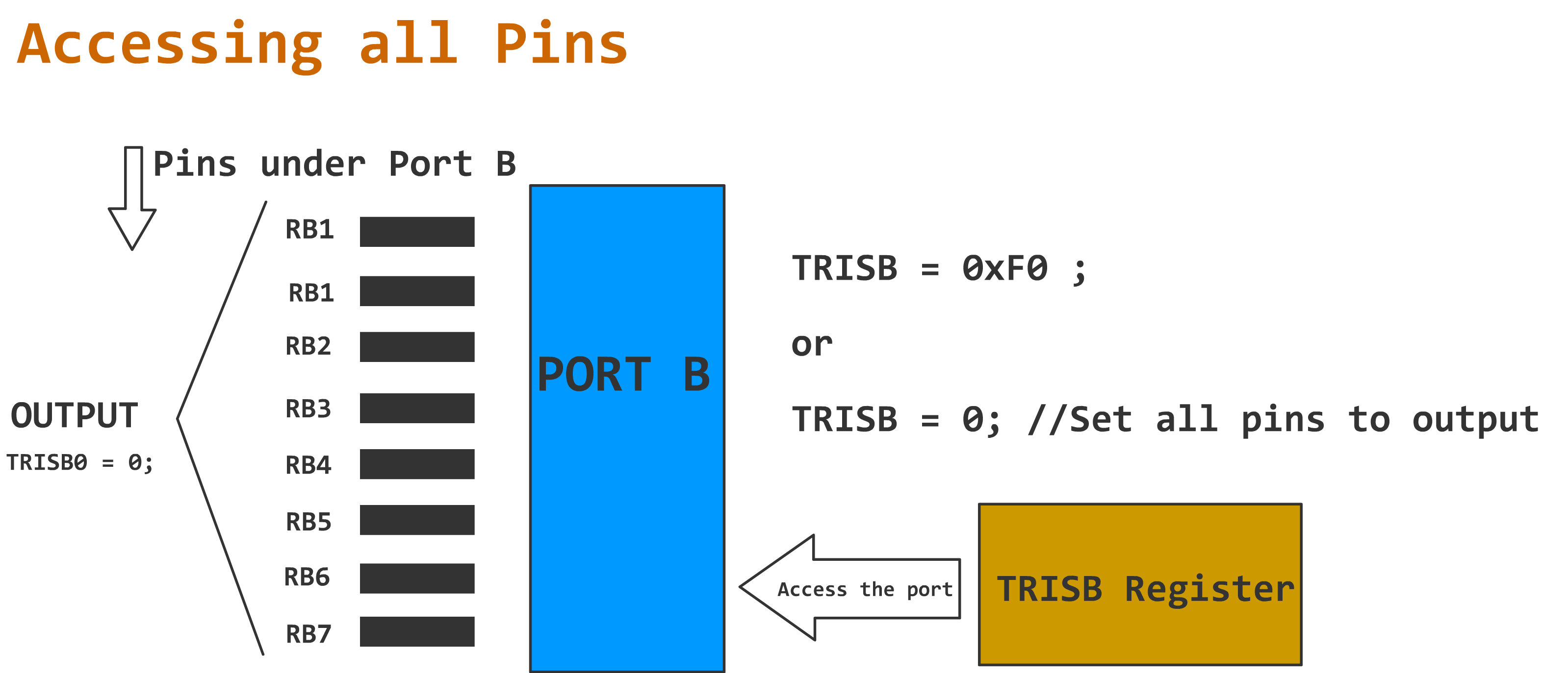
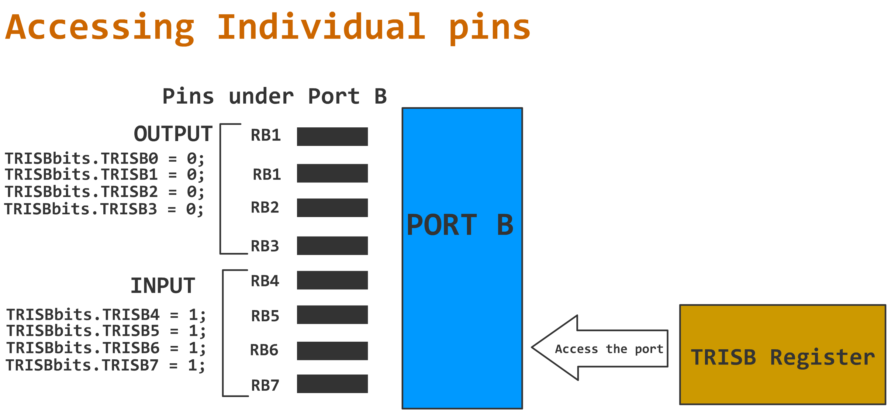
PIC18F4550 Programming Method 3 TRISB
PIC18f4550 ADCON Basics.
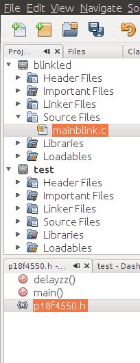
PIC18F programming | Using header files.
PIC18F4550 programming function prototypes
pic18f4550 Microcontroller Input methods
PIC18F Microcontroller Programming Tutorial
Tutorial Introduction
Welcome, here in this tutorial series we are going to learn some common methodologies for programming a pic18f. The tutorials here must be perfect to get you started with pic18f microcontroller. We are going to learn about the basics and various details that you need to consider while programming a pic18f microcontroller. For making life easy I have also attached relevant coding examples with explanation with each chapter of the tutorials that I am going to show. 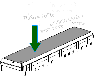
This tutorial is compiled for beginners with pic18f microcontrollers, who wish to learn microcontroller coding in Hardware C. We are also going to see the software tools, understand Microcontroller pin diagram, Ports and its relevance, Programming and relevant data sheet of the microcontroller, and I will also explain where and what to look for in a datasheet, as it can be confusing for beginner. Please do to complain if you find the tutorial a bit lengthy, but shortcuts are never good choice. A navigation menu on the Top must be helpful for you to switch between topic and chapters.
There are many ways or styles to code a simple microcontroller program. What is really necessary is to develop a perfect and good coding habit or methodology while you code, to avoid confusion. For doing a same logical operation there can be multiple ways in Hardware C. It will help you to optimize the coding you do.
Here I am going to explain some base line methods and also some common practices that you need to follow while coding a pic18f microcontroller with suitable examples. There can be hundred of ways of writing same code; I will just try to cover some of the basic styles to get you started, from Simple to complex ways. Once you understand the basics then it must be quiet easy for you to navigate your own imagination and make the microcontroller respond according to your wish. I will try to explain each and every block with simple and easily understandable format. I would also try to avoid Complex terms whenever it is possible.

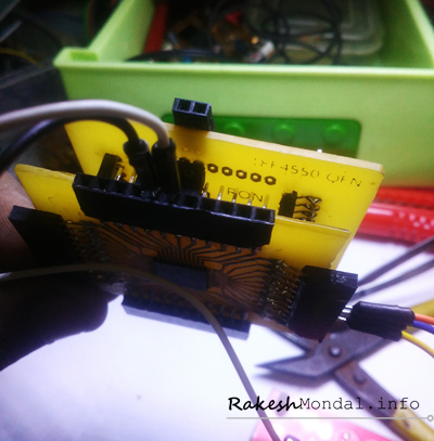
Pic microcontrollers are comparatively inexpensive and easy to find, there are also other microcontrollers Like Arduino Board which are little bit costly. Unless you want to spend too much for you projects, pic programming kit would be perfect to get you started. PIC18F is easily available and very powerful and quiet capable microcontroller which can easily enable you to add some Logic and Intel to your projects. All you need is a Microcontroller, An IDE and a Microcontroller programmer Like pickit2 or JDM.
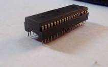
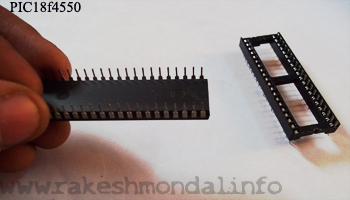
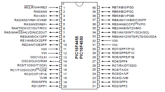
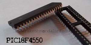
For our hardware C programming tutorial we are going to use a PIC18F4550 microcontroller. PIC18F4550 is a 40 pin microcontroller by microchip and it has been a favorite microcontroller in between microcontroller hobbyist. You can easily switch over to pic18f2550 microcontroller as well, with little modification in the code. However we are going to focus on pic18f4550 microcontroller for our tutorial with hardware C. After writing and understanding microcontroller Code we are going to upload the code into the microcontroller using hardware programmer.
If you wish to know in general about microcontroller when you can visit my What is a Microcontroller post. That should get you some basics of Microcontroller itself. For writing out first code we will need a microcontroller IDE and a Compiler to compile the microcontroller program.
Hardware C is similar to the general C software programming language that you compile with a BORLAND C compiler. However the compiler and Coding methods for Hardware C are going to be different. It depends upon the microcontroller. For coding a pic18f4550 you will need an IDE that supports the respective microcontroller and also a Compiler that can compile the code written on the IDE.
What is IDE? Don’t confuse IDE with “Integrated Device Electronics”, Here IDE is just an abbreviation for Integrated Development Environment which is a software environment for writing codes. IDE makes life really easy for coders.
Before we can Start coding we need out weapons.
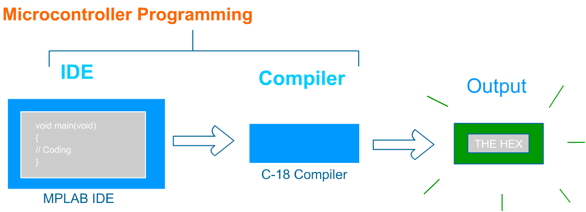
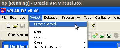
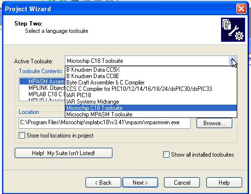
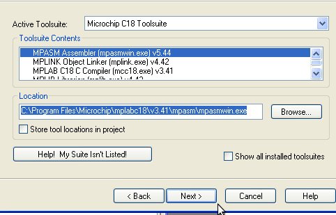
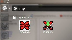
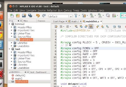
The IDE that we are going to use is microchips ”MPLAB IDE“and the compiler would be “ C18 compiler “ from Microchip . MPLAB IDE will help you with a Software platform where you can write your Hardware Code, ( Just like Eclipse IDE ). And the Compiler installed with MPLAB IDE will convert the Human written code into Machine language.
Please note that the microcontroller can only understand the machine language (0 and 1). The code [instructions] written in the IDE is converted into “Machine code” by the compiler. After compilation the output will be generated in .hex format (A filename with .hex) [ AN Example .hex ], all we have to do is just to upload that .HEX file into the microcontroller and then the pic18f4550 is ready for action.
There are different types of compiler. Suppose if you working with a PIC30F series microcontroller then the same MPLAB IDE will require a C30 Compiler engine to Compiler your code. C30 and C18 are just the versions of compiler which is capable of Converting your code into machine language (0’s and 1’s) which a microcontroller would understand.
However since we are going to use a “PIC18F“ series of microcontroller so we will use a C18 compiler.
A lite version of C18 compiler and MPLAB ide is completely free to download from Microchips website. Apart form C18 Compiler, a Hi-Tech C compiler can be also used for coding a pic18f4550 series of microcontroller. Hi-Tech C makes it easy to write codes specially when I prefer to write LCD programs, Hi-Tech C compiler is however not free if you wish to optimize the code, So we are going to Stick to C18 Compiler, lite version.
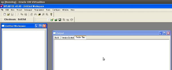
You need to login into microchip account which is free to create before you can download the C18 lite version and MPLAB IDE. The mplab refered in this tutorials is version v8.60. You can download the latest Release from their website directly.
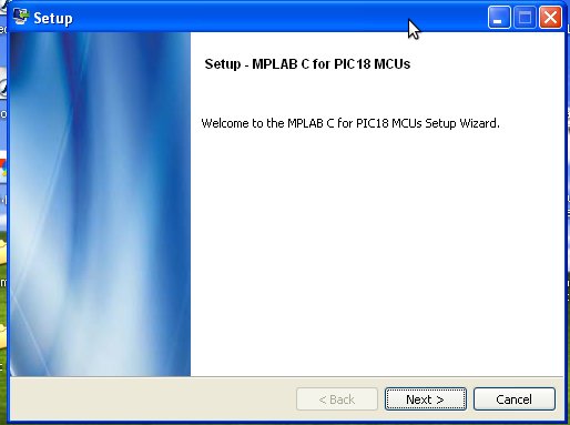
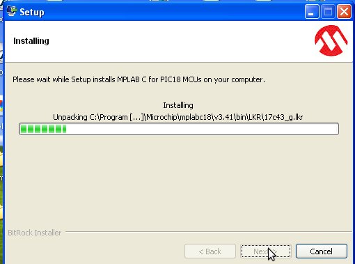
-DOWNLOAD C18 Lite Version Compiler
-DOWNLOAD MPLAB IDE
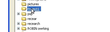
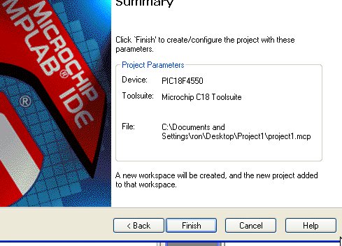
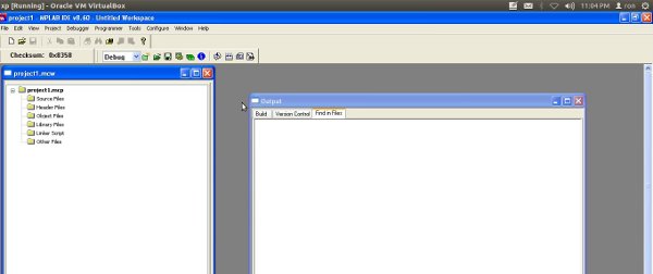
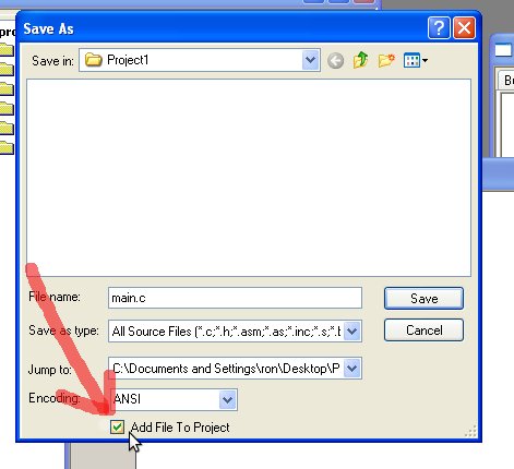
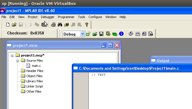
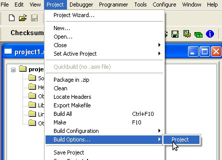
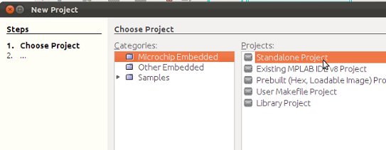
Once you are downloading the MPLAB and C18 Compiler then move on to next tutorial section which would deal with setting up your project for the first time.


Tutorial 3 - Blinking an LED Method-1
Tutorial 4- Blink LED Method-2 Header
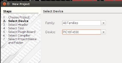
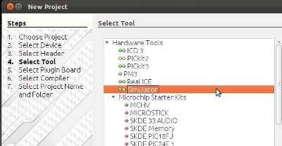
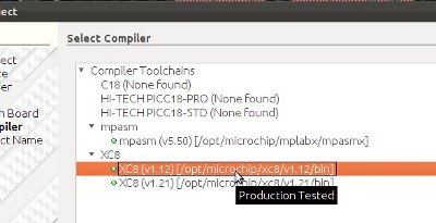
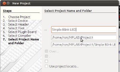
Tutorial 5- Blink LED -Mplab X IDE - XC8
PIC18F2550 - Blink LED - XC8 Compiler


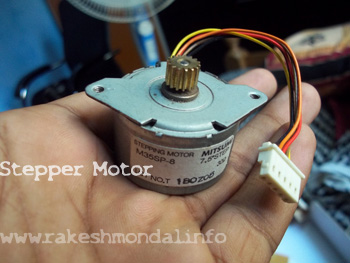
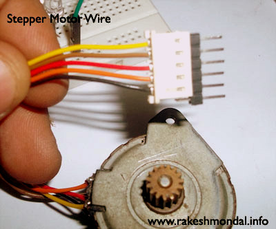


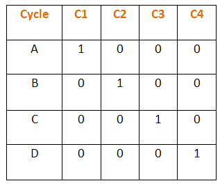


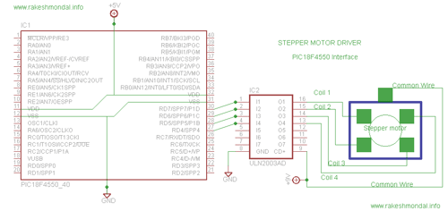
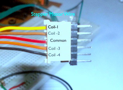
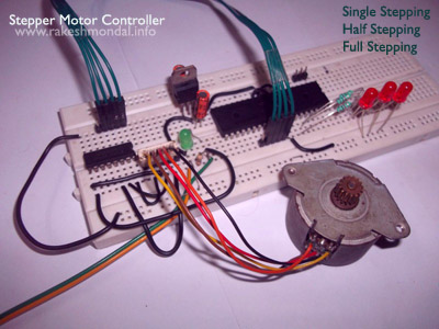
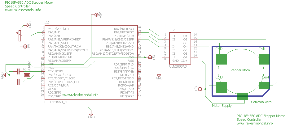
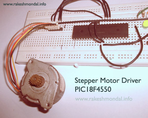 The first code demonstrates Single stepping mode for driving our 5 wire unipolar stepper Motor. Where the Stepper Motor coils are connected to PIC18F4550 pins, RD4, RD5, RD6 and RD7.
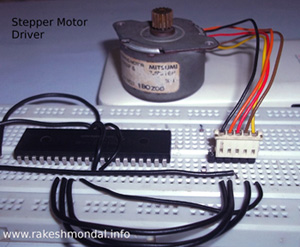
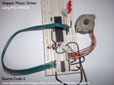
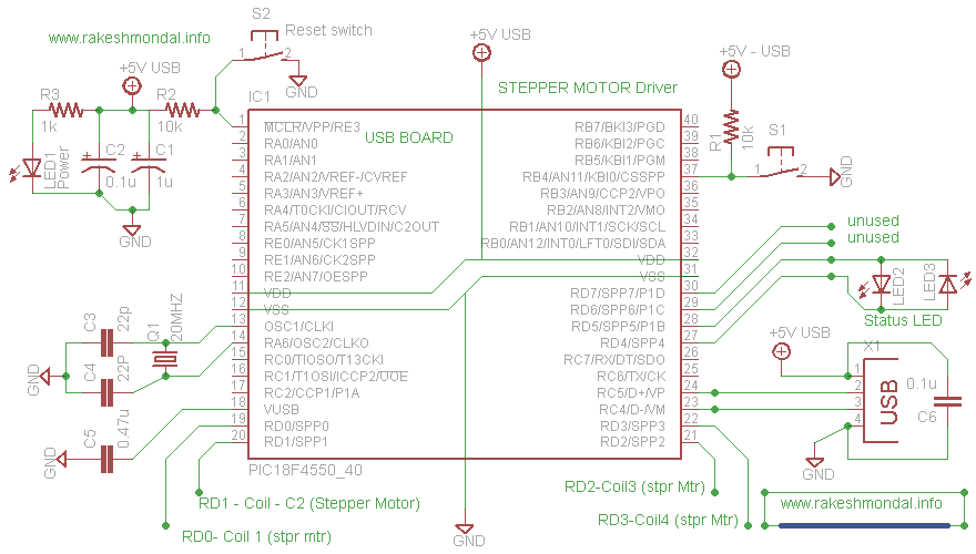
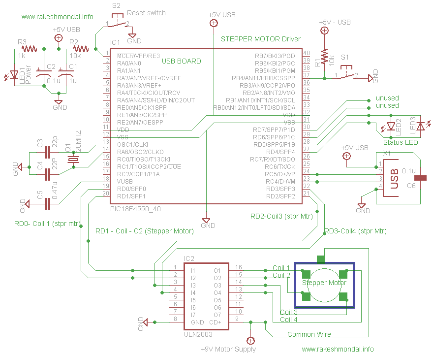
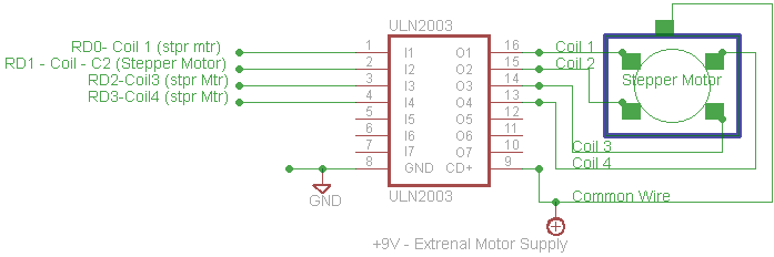
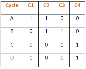
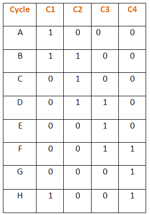
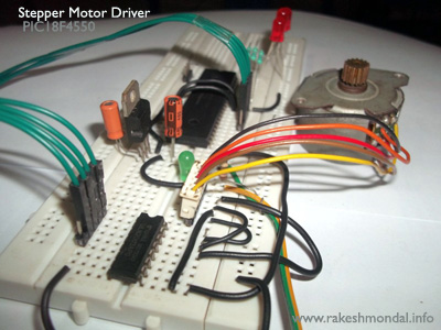 This source code demonstrates three modes of stepper motor which are Single stepping mode, half wave stepping mode and Full Wave stepping mode. Each mode executes for 5 to 6 seconds and then executes next mode. The schematic for this Source code is little different.